Because of its safety, simplicity, dependability and efficiency, the Universal Model 25 diesel engine has been chosen as standard on the Ericson 34. Diesel engines are subject to fewer adjustments and malfunctions than gasoline engines, once they are properly set up. Fuel contaminated by water or dirt, and the introduction of air into the fuel system cause the most common problems associated with diesel engine operation. As you will see, these problems are easily prevented by regular maintenance and the installation of a proper fuel filter/water separator with an adequate reservoir (standard on the Ericson 34).
Complete maintenance procedures and specifications are to be found in the "Universal Atomic Diesel Operation and Maintenance Manual", which you receive with your engine, (shipped aboard your new Ericson). Please read it before operating your engine and refer to it periodically for specifics, since only basic guidelines for safe operation and maintenance will be considered here.
Few skippers know enough about the care and operation of their engine and associated systems. Even if you find engine mechanics complex, you will find the mechanics of the Model 25 noticeably simpler than your automobile and familiarization in this area will greatly add to your self-sufficiency and enjoyment. Remember, your engine is also your battery-charging system and hot water generator at sea.
CAUTION: TO PREVENT DEADLY CARBON MONOXIDE POISONING SHOULD AN ENGINE EXHAUST LEAK DEVELOP, THE CABIN SHOULD BE ADEQUATELY YENTILATED WHENEVER THE ENGINE IS IN USE. IT IS SUGGESTED THAT, AT LEAST, THE TOP TWO CRIBBOARDS BE LEFT OUT OF THE MAIN COMPANIONWAY WHILE UNDER POWER.
3.1 Description
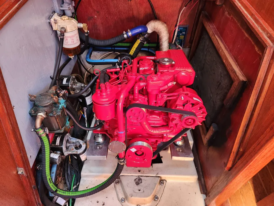
The Universal Model 25 is a 21 horsepower, 3-cylinder engine which provides adequate power for reserve, (adverse wind and wave conditions), as well as a generous amount of power for general use. It is installed with a "closed cooling system", cooled by circulation through a heat exchanger, which is cooled by the raw water system, circulating water from the intake thru-hull located under the galley sink cabinet and discharging it through the engine exhaust system. The closed (freshwater) cooling system also circulates through the water heater of the potable fresh water system, heating the water whenever the engine is is running.
Access to the engine is by removing the companionway stairs (lift them straight up) and then releasing the latches on the engine cover located just below the companionway. With the engine cover removed you will find the engine quite accessible, especially for fluid level and other routine checks.
3.2 Pre-Operation Checks and Starting Procedure
Before operating your engine:
- Read the specific owner's manual.
- Have the proper safety equipment aboard and know how to use it (see section 7.1 in this manual as well as U.S. Coast Guard Publications.)
- Make certain that the water heater tank, located under the cockpit behind the engine, is full. (see section 4.4.5 "Bleeding the Pressure Water System")
- Open engine compartment to check for fumes from fuel.
- Check engine crankcase oil and transmission fluid dipsticks for proper levels. Doing so will force you to open up the engine compartment, as well as insuring, by the most foolproof method, that proper levels of lubricants are maintained. Check beneath the engine for evidence of fluid leakage of any kind. NOTE: BE SURE THAT THE CRANKCASE OIL LEVEL DOES NOT GO ABOVE THE "FULL" MARK ON THE DIPSTICK, OR THE EXCESS WILL BE DISCHARGED THROUGH THE BREATHER INTO THE ENGINE PAN OR BILGE.
- Check to see that the engine cooling water intake valve is open (located under the galley sink)
- Check fresh water cooling level in coolant recovery tank in the starboard cockpit locker.
- Check to see that the fuel valve is open.
- Make sure that hoses and boat gear are clear of the propeller shaft.
- If the above items are in order, run the engine compartment exhaust blower for 5 minutes prior to starting the engine. To curb excessive power drain, the blower may be shut down during the starting process or after starting.
- Starting: Place shift lever in neutral position.
- Push throttle forward to the one-third open position, (the lever on the steering pedestal, with the red knob).
- Turn key to "on" position. This will activate fuel pump and oil pressure light. (optional oil pressure warning buzzer will sound, if installed). Be sure to lubricate the key switch regularly with light oil or WD40 to prevent it from sticking.
- Hold glow plug button switch in the "on" position while cranking the starter. The starter will not energize unless the glow plug switch is held in at the same time that the starter button switch is depressed. Depress the glow plug switch for about 20 seconds before pushing the start switch when starting a cold engine.
- After the engine is running, the oil pressure light should go out and the ammeter should indicate a charge.
- Check to see that water is coming from the exhaust thru-hull, located in the hull beneath the transom. Monitor the engine temperature, which should rise gradually to 175-185° F. If the oil pressure light remains on, or if not water is coming from the exhaust, or the temperature rises above the normal range, STOP THE ENGINE AT ONCE WITH THE STOP CABLE LOCATED JUST BELOW THE ENGINE INSTRUMENT PANEL IN THE COCKPIT. DO NOT TURN OFF THE KEY FIRST. The engine should still be in neutral. (See "Procedure for Stopping Engine").
- If all indications are normal, continue to run the engine for 10 minutes, monitoring the operating performance before leaving your dock or mooring.
- To Check the Transmission Operation: Check to see that the yacht is still well-tied to the berth. With the engine in idle, shift from neutral to forward and forward to neutral, then neutral to reverse and reverse to neutral. NOTE: Do not shift directly from forward to reverse or vice versa without pausing in neutral, and always be sure that the engine is at idle speed when shifting. NOTE: Do not "race" your engine in neutral.
- After stopping your engine, recheck oil and water levels so you're less likely to be surprised the next time you use it. CAUTION: COOLING SYSTEM WILL BE HOT AND UNDER PRESSURE, CHECK LEVEL IN COOLANT RECOVERY TANK IN STARBOARD COCKPIT LOCKER.
3.3 Procedure for Stopping Engine
- Throttle back to idle position.
- Place transmission lever to neutral (center position).
- Let engine engine idle for 1 minute to cool down.
- To stop engine, throttle back to the idle position and pull out the stop cable located to the right of the engine intrument panel in the cockpit. Be sure to push the stop cable back in after the engine stops -- if left out, it will prevent the engine from starting again.
- After the engine has stopped, turn off the key to shut off the electric fuel pump. CAUTION: DO NOT TURN OFF THE MAIN BATTERY SWITCH OR DISCONNECT THE BATTERY UNTIL THE ENGINE HAS STOPPED. DOING SO WILL LIKELY RESULT IN REGULATOR AND ALTERNATOR DAMAGE. CAUTION: DO NOT USE THE ENGINE DECOMPRESSION LEVER TO STOP THE ENGINE. SERIOUS DAMAGE TO THE EXHAUST VALVES MAY RESULT.
- When Shutting Down the Engine Under Sail: To prevent excess wear on the transmission, shaft and strut bearing, and also to reduce drag for more efficient sailing, be sure to place the transmission in reverse after the engine has been shut down while sailing. NOTE: LEAVING THE TRANSMISSION IN THE "FORWARD" POSITION WHILE SAILING, AFTER SHUTTING DOWN THE ENGINE, WILL "GLAZE THE TRANSMISSION PLATES AND CAUSE SLIPPAGE WHEN THE ENGINE IS RUNNING IN GEAR. When leaving your yacht, we recommend you turn off the fuel line valve (see fuel system diagram) and engine cooling raw water intake thru-hull valve. But, be sure to reopen them before restarting. Overheating by lack of raw water intake may result in damage to the pump impeller (carry a spare), or more serious engine damage. Starving the engine for fuel by leaving the fuel shut-off closed will require re-bleeding the fuel system before the engine may be restarted. (See the engine owner's manual for fuel system bleeding procedure.)
3.4 Starting the Engine with a Weak Battery
The Universal Model 25 has been fitted with a decompression lever, located on top of the forward end of the engine, to aid in starting when battery cranking power is weak.
The procedure for using the decompression lever while starting, as stated in the engine manual, follows:
- Set gear shift to neutral and advance throttle to 1/3 open.
- Pull decompression lever to release position.
- Energize glow plugs.
- Turn ignition switch to "start" position to "spin" the engine.
- After 3 to 5 seconds, when the engine has gained momentum, return decompression lever to its original position. Engine should now start.
3.5 Troubleshooting and Maintenance
This section will deal with maintenance considerations and potential problems in these areas:
- Engine overheating
- Fuel System
- Vibration
- Propeller shaft packing gland
3.5.1 Engine Overheating
After checking that the raw water intake thru-hull is open, check the water pump impeller for excessive wear or damage. Replace if needed. If the impeller looks good, again check to be sure that the thru-hull is open and disconnect the intake hose at the thru-hull to see if water flows in at a steady rate. If not, debris (such as a plastic bag) or marine growth may be blocking the thru-hull. If underway under power, sometimes shutting the engine down to stop intake suction will allow the debris to float off the intake thru-hull. Try this and perform the thru-hull check. In other cases, an engine will not show signs of overheating until underway. This is sometimes a result of hair like growth in the area of the intake that only moves across the opening when the boat is in motion. Rigorous annual maintenance and periodic cleaning and inspection by a diver can prevent such aggravating situations.
Your Ericson 34 is also equipped with a water heater on the fresh water system (see section 4.4.3). The water heater works on a heat-exchanger principle by circulating the fresh cooling water from the exhaust manifold side of the engine (from the themostat housing, on later engines), to the water heater heat exchanger and back to the engine heat exhanger on the aft end of the engine. (See diagrams for both plumbing routes on the following pages).
Extra consideration may need to be given to bleeding air from both the water heater and engine Cooling hoses leading to and from the water heater. Follow the instructions in "Plumbing", section 4.4, for bleeding the pressure fresh water system. To bleed the engine fresh water system, check coolant level after running the engine for the first time and add coolant as necessary. If a "bubble" develops in the cooling hose, allow the engine to cool and then complete filling of the system. Be sure to maintain the proper anti-freeze mix.
CAUTION: DO NOT ATTEMPT TO REMOVE ANY HOSES OR OPEN THE COOLING THE COOLANT IS UNDER SYSTEM CAP ON THE ENGINE WHILE THE ENGINE IS HOT HIGH PRESSURE AND TEMPERATURE, AND CAN CAUSE INJURY. ALLOW THE ENGINE TO COOL, OR ADD COOLANT THROUGH THE RECOVERY SYSTEM IN THE STARBOARD COCKPIT SEAT LOCKER.
3.5.2 Fuel System
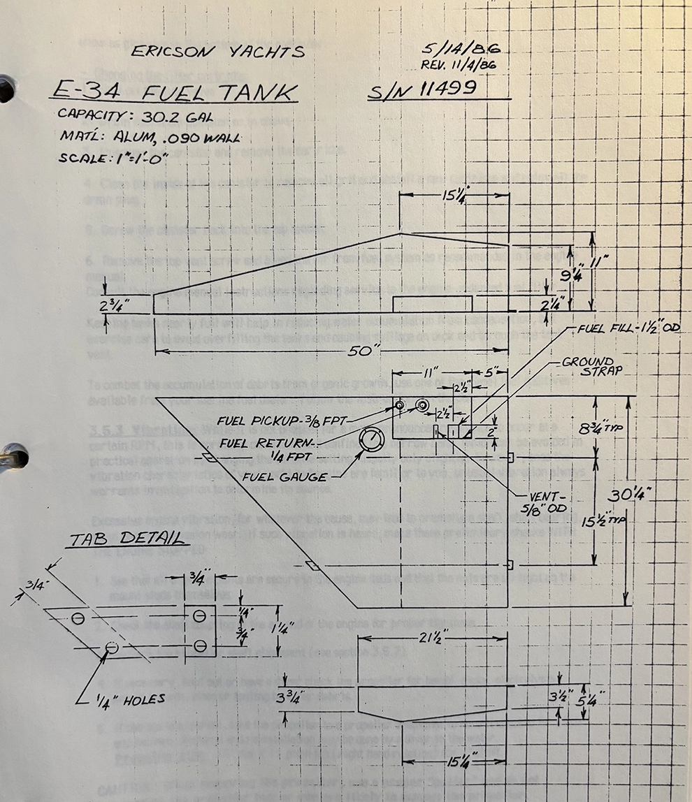
A 30 gallon aluminum fuel tank is located under the quarter berth. It is secured in place with four welded tabs which are screwed into recesses in the bunk top. The fuel pick-up, fuel return, and fuel guage are located in a recess on the forward end of the tank. The fuel fill hose fitting, vent fitting and grounding lug are located on the aft side of the recess. (see Fuel Tank diagram following page).
The fuel gauge is a mechanical float type with magnetic drive. This "direct" read type of gauge is the most dependable type for sailboat use, especially since fuel consumption is low. The magnetic drive feature allows the gauge to be changed without removing the unit from the tank.
The tank is electrically bonded from the welded on ground lug to the engine and to the deck "Diesel" fill pipe to prevent static sparking.
Moisture, contamination and air will all cause a diesel engine not to run and possibly damage the injector pump and injectors. To help prevent intrusion of contaminants into the engine, an in-line fuel filter is supplied as standard equipment by Ericson, in addition to the canister-type filter mounted on the engine. You should become familiar with the service procedures for both. Filter type: "Racor" (220R).
The fuel filter performs two functions:
- As a filter, to remove debris and contaminants which may be introduced into the system from supply tanks where fuel is purchased, or possibly from your own tank from organisms growing between the fuel and condensation water in the boat's fuel tank. Filtering suspect fuel as it enters the tank also helps keep contaminants out of the fuel system.
- As a water separator, removing moisture from condensation in any airspace inside the tank, or that which may have been introduced from your supplier's storage tank.
Basic maintenance - draining water from the reservoir drain plug, and replacing the filter cartridge will help prevent inconvenient inoperation and costly engine repair.
CAUTION: EXCESS WATER ACCUMULATION IN THE FILTER CAN OVERBURDEN IT, ALLOWING WATER TO PASS INTO THE INJECTOR SYSTEM. CHECK THE FILTER FREQUENTLY.
Servicing the in-line fuel filter -
- Water removal:
Have on hand a small can which will fit under the filter, and rags to clean up any spillage. Unscrew the drain plug from the bottom of the filter canister and allow the contents to drain for a few seconds. Replace the plug and check the contents of the can for dirt and water.
Water will show as globules in the bottom of the container.
Changing the filter cartridge:
- Shut off the fuel valve.
- Drain fuel from canister as in above.
- Unscrew the canister and remove the cartridge.
- Clean the inside of the canister to remove all grit and install a new cartridge and reinstall the drain plug.
- Screw the canister back into the top mount.
- Remove the top vent screw and bleed the air from fuel system as recommended in the engine manual.
Consult the engine manual instructions regarding service to the engine-mounted fuel filter.
Keeping tanks nearly full will help in reducing water accumulation from condensation, but exercise care to avoid overfilling the tanks and causing spillage on deck and through the tank vent.
To combat the accumulation of debris from organic growth, use one of the diesel fuel additives available from your marine fuel dealer. Follow the instructions on the can.
3.5.3 Vibration
While it is not unusual for a more pronounced resonance to occur at a certain RPM, this is normally consistent and confined to a narrow band, which can be avoided in practical operation by changing the throttle setting, usually only slightly. However, once the vibration characteristics of your yacht and engine are familiar to you, unusual vibration always warrants investigation to determine its source.
Excessive engine vibration, for whatever the cause, may lead to premature shaft, shaft bearing, strut and transmission wear. If such vibration is heard, make these preliminary checks WITH THE ENGINE STOPPED:
- See that all engine mounts are secure to the engine beds and that the nuts are all tight on the mount studs themselves.
- Check the shaft coupling at the aft end of the engine for proper tightness.
- Recheck the propeller shaft alignment (see section 3.5.7).
- If necessary, haul out or have a diver check the propeller for bends, nicks, electrolysis excess growth, lines or fouling by other debris.
- If damage is apparent, take the propeller to a propeller specialist to have it checked for pitch and balance. Removal and reinstallation may be done by a diver in the water. Propeller size: 15" dia. X 11 pitch RH (right hand rotation) for 1" shaft.
CAUTION: When removing the propeller, use a proper "puller" and do not hammer on the propeller hub or you are likely to damage the propeller.
3.5.4 Propeller Shaft Packing Gland
The packing gland or "stuffing box" is mounted on a rubber coupling which is clamped to the shaft tube in the hull where the shaft passes through the hull aft of the engine. It consists of one large bronze nut inside which, are 2-3 turns of 1/8" waxed flax packing. A locknut against the gland nut holds it to the desired adjustment. The packing gland functions to seal out most of the water from entering the hull where the shaft passes through to the outside, while at the same time, allowing just enough water between the shaft and the packing gland to lubricate and keep the shaft from heating up from the friction of the seal.
Worn packing or a poorly adjusted packing gland nut will allow too much water to enter causing a nuisance, or worse, causing the boat to sink if it is left unattended for a long time. Too little water entering will cause reduced engine efficiency and premature shaft and packing wear. Excessive shaft and packing wear will eventually make it impossible to adjust the packing nut properly.
Adjustment procedure:
Ideally, the propeller shaft packing gland should be adjusted so that with the engine running in gear (shaft turning), 5 or 6 drops per minute should enter from between the shaft and the packing nut. With the shaft stationary, no water should enter. However, it is not always possible to achieve a complete water stoppage with the shaft stopped. Occasional dripping is acceptable.
Access for maintenance and adjustment of the packing gland is through the starboard cockpit seat hatch by removing the fabric curtain between the seat locker area and the aft end of the engine compartment. Observe the packing gland with the shaft turning.
If the shaft is leaking too much:
- Stop the engine
- Loosen the lock nut using two pair of large channel-lock pliers. Try not to squeeze too hard, it is a rather thin nut and excessive pressure may distort it.
- Tighten the packing nut by turning it 1/2 turn clockwise (if viewed from its forward end facing aft). Note that the packing nut does not have to feel tight to be properly adjusted.
- While holding the packing nut in position, tighten up on the locknut until it is snug against the packing nut.
- Restart the engine. Place it in gear and recheck the gland. If it is still allowing too much water in, stop the engine and readjust as necessary.
If all the adjustment is taken out of the packing nut and the shaft is still leaking excessively, especially when the shaft is not turning, the packing will need to be replaced.
To replace the packing:
- Have on hand about 12 inches of 1/8" waxed flax packing, (there will be some excess).
- Loosen the locknut as described in step 2 above.
- Loosen the packing nut, so that it comes all the way off the bronze threaded nipple. This should expose the packing around the shaft. If you are performing this operation in the water, a steady stream of water will now be running into the boat. This no need to be concerned since the entire changing process does not take long enough to allow a significant amount of water to enter. Note: The hose clamp around the shaft, which is just aft of the coupling, may require removal in order to be able to slide the packing nut far enough forward to expose the packing. Be sure to reinstall it, since it is there to prevent the shaft from backing out of the tube if the shaft should ever slip from the coupling.
- Carefully remove all of the old packing, but do not discard yet. Keep it available in case there is some unforseen problem with the new packing material. Note: The packing is installed in a series of three rings butting, rather than spiralling.
- Although, in the final installation, the packing is not spiralled around the shaft inside the nut, it is easy to measure and score all the turns simultaneously by spiralling three turns and then dragging a knife blade across them as shown in the illustration. Unwrap the turns and complete the cuts to form three separate rings.
- Line the rings on the shaft next to the bronze nipple. Be sure that the length of each is just the circumference of the shaft. If they are too short, they will leak where the ends butt together and, if too long, they will tend to bunch and make it difficult to reinstall and adjust the packing nut. Position the butt joints so that they do not align from one ring to the next.
- With the packing in place, slide the packing nut back into position, and thread it back onto the bronze nipple.
- Adjust the packing gland as described above.
3.5.5 Propeller Shaft Strut Bearing
The propeller shaft strut bearing is a bronze and rubber press-fit insert between the shaft and the shaft strut which supports the aft end of the propeller shaft. It should be inspected closely at each annual haul-out and in between by a diver, if excess vibration is experienced.
The most common cause for premature strut bearing wear is excessive vibration caused by improper alignment (see section 3.5.7) or by a bent, damaged or marine growth-fouled prop. As bearing wear increases, so does vibration.
Replacing the strut bearing is normally not a difficult task, however, time, corrosion and wear sometimes make it difficult to extract. It is also easier to remove with the shaft out of the boat - nessitating removal of the rudder - so, the job is easier done out of the water.
- With the prop shaft removed, using a brass or aluminum drift or a section of tubing about the size of the outside diameter of the strut bearing, tap it out with a hammer. In some cases, fairly solid hits with the hammer will be required. Do not hit the bearing hard enough to risk damaging the strut itself. If this becomes a risk, go on to step 2.
- If the bearing will not slide by the above method, use a hacksaw to score the inside of the bearing in several places. Reassemble the hacksaw blade to the saw frame with the blade running through the bearing and cut the strut bearing. BE CAREFUL NOT TO CUT DEEP ENOUGH TO SCORE THE STRUT ITSELF.
- With the old bearing removed, insert the new bearing by tapping it in with a hammer and a block of wood between the bearing and the hammer. DO NOT STRIKE THE BEARING DIRECTLY WITH THE HAMMER SINCE THE BEARING SLEEVE WILL DEFORM. BEARING DIMENSION: 1 1/4" O.D. X 3 7/8" L. for a 1" shaft.
3.5.6. Propeller Shaft
The propeller shaft on the Ericson 34 is made of 1" diameter Monel. It is attached at the engine end by insertion into the shaft coupling with a key and two setscrews, which are safety-wired to prevent them from backing out. A periodic inspection should be made to be sure that the wire is in place and in good condition. A hose clamp should be in place on the shaft between the packing gland and the engine coupling to prevent the shaft from backing out of the shaft tube, damaging the rudder and allowing water to enter, should the shaft slip from the coupling.
Shaft Removal:
Removal of the propeller shaft is a job that is best left to a well-equipped boat yard, in most cases. The rudder must be removed, to allow room for the shaft to slide out. Additionally, the shaft is very difficult to remove from the coupling after time. Rudder removal, necessites removal of the steering quadrant. If long-range cruising takes you well beyond the proximity of boatyard services but, conditions require that you remove the shaft, use the following procedure:
- Remove the safety wire and the shaft setscrews. Uncouple the shaft coupling from the engine half of the coupling. Remove the hose clamp from the shaft and slide the shaft back away from the engine. Try, with a wooden or plastic mallet, to tap the coupling from the shaft. If this method fails, move on to step 2.
- With the coupling still separated from the engine, insert a short 1/2" diameter hex-head bolt between the center of the engine half of the coupling (which is solid) and the shaft half, which is bored through, exposing the forward end of the shaft. The hex head bolt should be as long as possible and still allow enough of the threads on the coupling bolts to go into the engine half of the coupling.
- Begin to tighten all of the coupling bolts evenly. They will be quite tight, but should begin to move the shaft aft out of the coupling as the two couplings are drawn together. Longer lengths of 1/2" bolts may be required as spacers as the shaft moves back out of the coupling.
Shaft Reinstallation:
- Slide the shaft forward into the boat. Check to see that the packing is not damaged in this process. You may want to change it as a matter of timely maintenance.
- Place the key in the keyway and slide or tap the shaft coupling back onto the shaft. The fit should be fairly snug. Note: To make future shaft removal easier, we would recommend coating the forward end of the shaft with "never-seez" where it inserts into the coupling.
- Install the setscrews and safety wire them.
- Recheck the shaft and engine alignment on recoupling of the shaft to the engine. (See Section 3.5.7)
3.5.7. Engine/Shaft Alignment
The importance of proper engine/shaft alignment is pointed out in Section 3.5.3 on vibration. As a result of shipping and use, the hull and components flex to some extent. Although this may not be readily discernible and, although the Triaxial Force Grid system will minimize vibration, shaft alignment tolerances are very small (.003").
Initial engine alignment is done during the installation of the engine and components during construction. Your dealer, again, checks alignment during the commissioning of your yacht. Afterward, alignment checks should take place annually, in the event of impact to the propeller/shaft/strut, if abnormal vibration is experienced, and every time after your yacht is launched after haulout.
Engine Alignments should be done in the water as follows:
- Remove the bolts holding the shaft half of the coupling flange to the engine half of the coupling flange.
- Slide the shaft coupling up against the face of the engine coupling, if it has slid back at all.
- Check all around the coupling joint with a feeler guage. If any thicker than .003" can be inserted between the two faces, the engine mounts must be adjusted until the face of the engine half of the coupling lines up with the shaft half and no gaps larger than .003" are found.
- To adjust the engine up or down, slack the nuts on the engine mount studs. To adjust the engine sideways, loosen the lag screws holding the mount bases to the engine beds.
- When the alignment checks, retighten all mount nuts and screws. Recheck to make sure that retightening did not cause any misalignment.
- Now rotate the shaft and its flange 90 degrees to each fastener position and recheck the alignment. This check will determine if the coupling is sitting true on the shaft, or if the shaft is bent.
- Reinstall all four coupling screws and tighten them evenly.
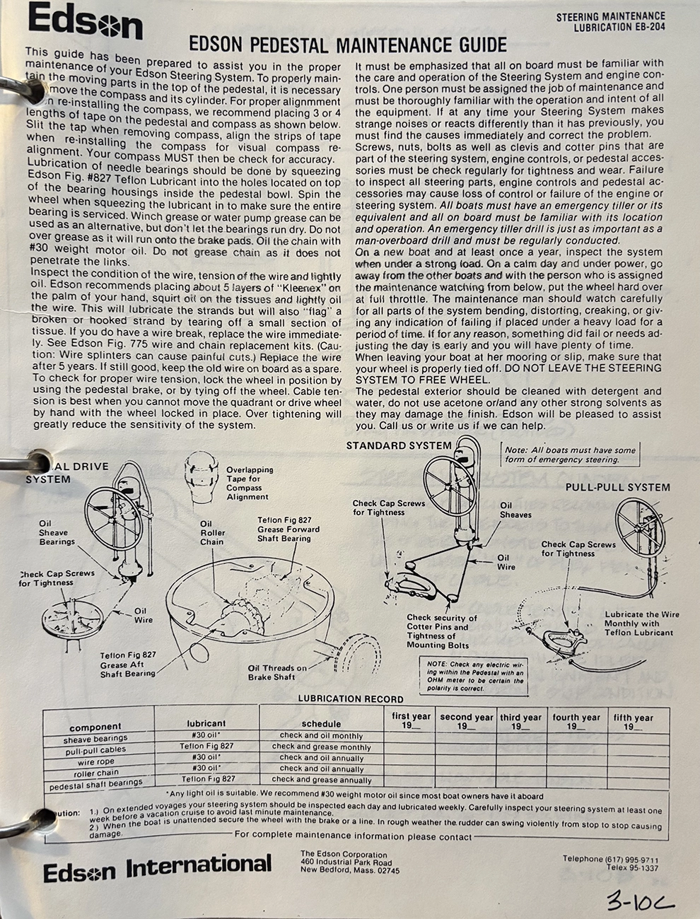
3.6 Steering System
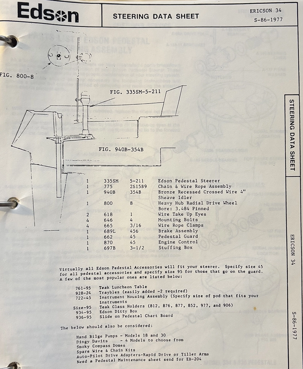
Your Ericson 34 comes equipped with pedestal steering with a 36" destroyer wheel, brake, pedestal guard, and engine controls mounted on the steering pedestal. Inside the pedestal a roller chain turns over a sprocket on the wheel shaft. The chain joins a cable at each of its ends which then runs through the cockpit sole via 2 sets of sheaves and to the rudder quadrant, which clamps and bolts onto the rudder shaft.
At each quadrant/cable attachment point there is an eyebolt which allows steering tension and wheel spoke centering to be done. Each eyebolt is locked into the desired tension with a set of two jamming nuts.
An Emergency Tiller is supplied to be used in the event of a failure of the wheel steering system. To install it, unscrew the cover plate on the cockpit sole just aft of the pedestal. This will expose the rudder post. Insert the shaft of the tiller into the rudder post and the emergency steering system is functional. Removing the wheel at this point will increase operating room.
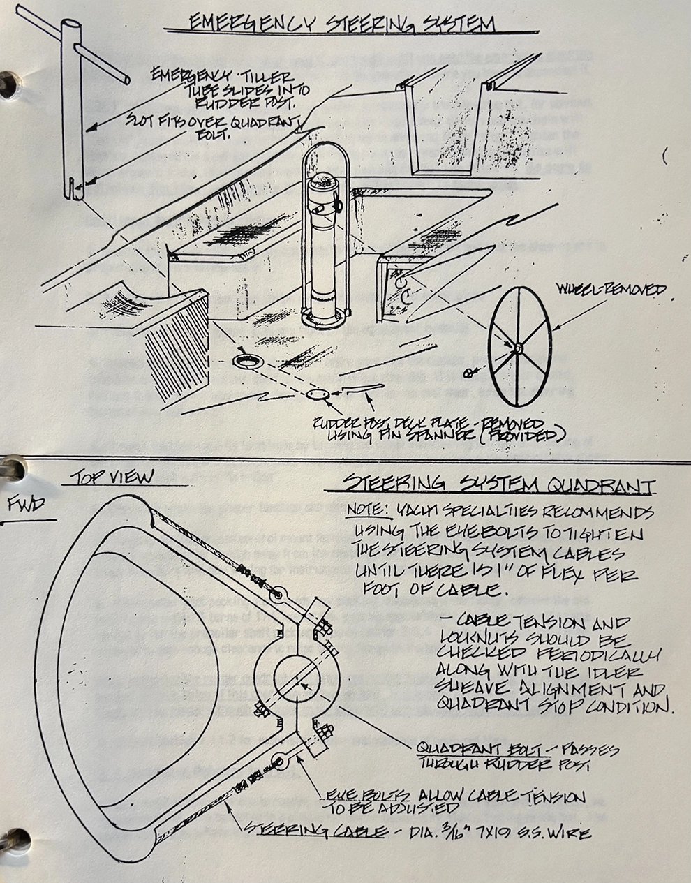
A suggestion: although you may never need it, don't wait until you need the emergency steering system to use it. Try it and become familiar with its operation before you have to depend on it.
3.6.1 Maintenance
The wheel steering system is relatively trouble-free but, for obvious reasons, should receive critical inspection frequently. Cables may stretch and the chain will "run-in", contributing to slack in the system causing an annoying lag or "slop". Tighten the steering cables at the quadrant until the steering is positive. Overtightening the cables will cause excess friction, making steering more laborious and the feel less sensitive. Be sure to retighten the jam-nuts properly after the adjustment is completed.
Additional maintenance items:
- Inspect the fasteners in all sheave mounts to be sure they are tight and that the sheaves are in proper alignment with the cable.
- See that all of the cotter pins which secure the sheave pins are in place.
- Make certain that the jam-nuts are tight on the adjustment eyebolts.
- Inspect the cables for general condition. Make sure that the clamps, press fittings and thimbles are in good condition and that the cable is not stranded. If it looks worn or chafed, replace it and find out why is was damaged if other than by normal wear, since the steering cables should last years.
- Inspect the chain and its terminals by turning the wheel and viewing it from both the top of the pedestal and below the cockpit sole. Lubricate the chain twice a year with light oil or a spray teflon lubricant such as "Tri-flon".
- Check the brake for proper function and adjustment.
- Check to see that engine control mount fasteners are all properly tight and that engine control cables are secured far enough away from the chain and sprocket so that chafing will not occur. Check to be sure that any wiring for instruments or compass light is likewise protected.
- If the rudder post packing gland needs new packing, disassemble the flange, remove the old packing and install 3 turns of 1/4" waxed flax packing approximately 12" long. Use the same method as for the propeller shaft packing gland in Section 3.5.4. The quadrant may need to be removed to gain enough clearance to raise the top flange on the packing gland. Note: Removing the rudder quadrant will allow the rudder to drop. Be sure that the rudder is supported from below if this operation is done on land. If it is done in the water, an extra set of hands will be needed although the foam in the blade will provide some measure of bouancy.
- Consult Section 1.11.2 for associated rudder maintenance at haul-out time.
3.7 Suggested Onboard Tool Kit
Since a metal toolbox is prone to rusting and its sharp edges may scratch wood and fiberglass, we recommend that tools be stored in a plastic toolbox or heavy-duty plastic fishing tackle box. The tackle box may also have trays for small parts and miscellaneous spare fasteners.
At sea, a critical situation could call for the use of dependable tools -- be sure that those in your toolbox would be up to the task. "Bargain-price" tools will not only fail to get the job done but, may cause injury as well. Sear's Craftsman brand is one of the dependable brands available and suitable for onboard use. A suggested list of tools appears below in the general order of importance:
- 1ea - Large "Vise-Grip" (recommended brand name)
- 1ea - Small "Vise-Grip"
- 1 set - Open end Wrenches 3/8"-3/4"
- 1ea - 12" Adjustable Wrench
- 1ea - 8" Adjustable Wrench
- 1ea - Hacksaw with extra blades
- 1ea - Awl
- lea - 3/8" (large) Blade Screwdriver lea - 1/4" (medium) Blade Screwdriver 1ea - Philips Screwdriver (large)
- 1ea - Philips Screwdriver (medium)
- 1ea - Standard Pliers
- 1ea - Long-nose Pliers
- 2e8 - Large Slip-joint Pliers (to fit shaft packing gland)
- lea - Hammer
- 1set - 3/8" Drive Sockets: 3/8" - 3/4" with universal and extensions
The above is a minimum list of tools which you should have at your disposal. Performing maintenance and outfitting your Ericson 34 with items for your personal needs will indicate to you which additional tools would be helpful, especially if extended cruising is planned. A hand drill and bits, assortment of punches, multimeter, etc., are all items which might prove helpful and bolster your self-sufficiency. It is also recommended that you carry some type of pocket knife and keep it sharp! The Swiss Army Knife is probably the handiest.
While you are assembling your tool kit, you should also consider assembling a sail repair kit of needles, thread, sail twine, sewing palm, extra dacron and self-adhesive dacron. These items should be stowed in a bag or pouch separate from the onboard tools. Your sailmaker can help with supplies for a sail repair kit, and some sailmakers have them preassembled.